.jpg)
.jpg)
E2A6D7D285CC4CE39C46554608080E04.jpg)







Description
-
BrandBently Nevada
-
Model3500/40-01-00-R0
-
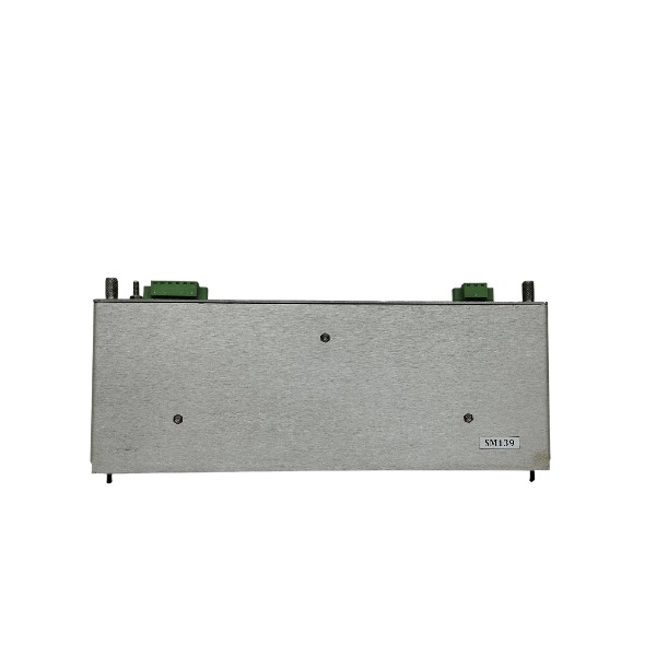
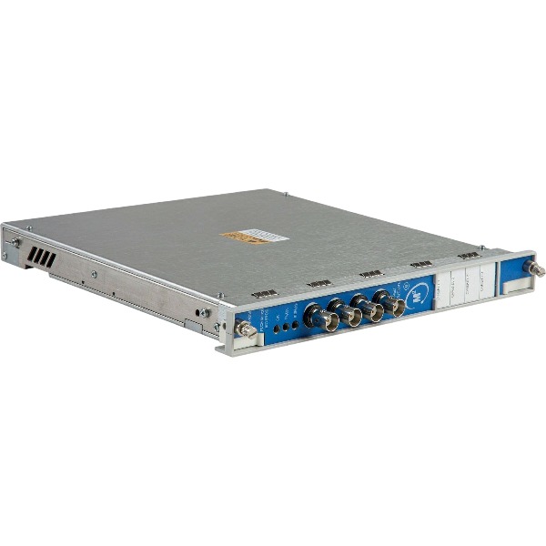
Product NameProximitor Monitor Module
-
Place of OriginUnited States
-
Customs HS Code85371011
-
Power Supply+5Vdc from 3500 rack backplane
-
Dimensions304.8 mm × 203.2 mm × 30.5 mm
-
Weight0.85 kg
-
Operating Temperature-30℃ to +65℃
-
Storage Temperature-40℃ to +85℃
-
Warranty12 month
-
Product Statusoriginal
Working Principle of Bently Nevada 3500/40-01-00-R0
The 3500/40 is a four-channel vibration and gap monitoring module built for the Bently Nevada 3500 rack system. It primarily measures shaft relative vibration and shaft clearance using signals from eddy current proximity transducers. The module acquires signals from eddy current probes, processes measurement data, executes alarm logic, delivers 4-20mA analog outputs and relay contact status, and exchanges data with other modules through the rack backplane.
Power Supply & Backplane Communication
The module obtains its DC operating power from the 3500 rack backplane, which is energized by the 3500/15 power supply module. It communicates with the rack interface module (3500/22M) and other monitoring modules via the backplane bus. Measured values, alarm states and fault information are uploaded to the rack controller for local display and external transmission. No standalone external DC power supply is required for this monitor module.
Eddy Current Sensor Excitation & Signal Acquisition
The module supplies regulated +15V DC excitation power to each connected eddy current proximitor. The proximitor converts this DC power into a high-frequency alternating magnetic field radiated from the probe tip. As the conductive metal shaft moves toward the probe, eddy currents form on the shaft surface. The coil impedance of the probe varies according to the gap distance between the probe tip and shaft surface. The proximitor translates such impedance change into a continuous analog voltage signal proportional to the clearance. The 3500/40 module captures this voltage signal via its input terminals.
Signal Conditioning & Data Conversion
Raw analog gap signals feed into the internal signal conditioning circuitry of the 3500/40. This circuitry filters high-frequency noise and suppresses interference. A high-resolution ADC then converts the conditioned analog signals into digital values. Using the preloaded probe calibration curve, the module converts voltage readings into physical engineering units: gap (mil or μm) and peak-to-peak vibration amplitude. It can extract both dynamic vibration waveforms and static gap values simultaneously from one single input signal.
Measurement Calculation
Static gap measurement: Indicates the average distance between probe tip and shaft, used to evaluate shaft installation misalignment and probe mounting clearance.
Dynamic vibration measurement: Separates the alternating vibration component from the input signal to calculate peak-to-peak shaft relative vibration, reflecting shaft whirl and oscillation.
When configured as a Keyphasor channel: The module captures the once-per-revolution pulse from the Keyphasor probe to compute rotational speed and phase angle for vibration spectrum analysis.
Alarm & Danger Threshold Comparison Logic
Two threshold levels, Alert and Danger (Trip), are defined by users using the 3500 configuration software. The module continuously compares real-time vibration or gap readings against these preset thresholds.
When the measured value exceeds the Alert threshold: the module activates the Alert status and triggers the corresponding Alert relay contact.
When the measured value exceeds the Danger threshold: the module activates the Danger status and triggers the Danger relay contact. The module also identifies transducer faults such as open circuits, short circuits and out-of-range gaps, and generates sensor fault alarms accordingly.
Isolated 4-20mA Analog Output Conversion
The module converts measured vibration or gap values into galvanically isolated 4–20mA current signals. 4mA represents the lower limit of the measuring range while 20mA corresponds to the upper limit. This isolated analog signal is transmitted to DCS or PLC systems for remote indication and closed-loop monitoring. The 4-20mA current loop is electrically isolated from the probe input circuit to prevent cross interference.
Relay Dry Contact Output
Alert and Danger statuses are output via passive dry relay contacts on the rear terminal block. NO, NC and COM contact terminals are available. These contacts carry no voltage output; external power must be provided by the user’s interlock or trip circuit to implement protection logic and equipment trip actions.
Fault Diagnostics & Data Upload
Built-in self-diagnostic circuits continuously check module hardware integrity, probe cable continuity and signal validity. Detected faults, alarm events and waveform records are sent to the rack interface module through the backplane. Operators can view real-time readings, alarm logs and oscillography through configuration software or the upper-level monitoring system.
System Integration
All measurement parameters, alarm thresholds, probe model and cable length settings are saved to the module’s non-volatile memory after downloading. As a core component of the 3500 rack protection system, this module is widely deployed on steam turbines, gas turbines, compressors and other large rotating machinery to implement shaft vibration and shaft clearance protection.

Rack Backplane Power Wiring
The module receives operating power via the internal backplane of the 3500 rack. No independent external power wiring is required for this monitor module. The rack power source is provided by the 3500/15 power supply module. The backplane bus handles both power distribution and inter-module communication within the rack.
Eddy Current Probe Input Wiring (4 independent channels)
Each signal path follows the sequence: Probe → Extension Cable → 3500/40 rear I/O terminal block. Terminal definition for each channel: +15Vdc (sensor excitation supply), COM (common ground), SIG (signal).
+15Vdc: Connect to the positive conductor of the proximitor extension cable
COM: Common return path for probe power and signal
SIG: Vibration and gap signal conductor
The total combined length of probe plus extension cable must match the parameter settings downloaded to the module. Use genuine Bently Nevada triaxial shielded cable.
4-20mA Analog Output Wiring
Each measurement channel supports galvanically isolated 4-20mA output for transmission to DCS or PLC systems. Two terminals are available per channel: AO+, AO-.
Wiring instruction: Connect AO+ to the positive input terminal of the remote analog acquisition card; connect AO- to the negative input terminal of the remote analog acquisition card. The 4-20mA current loop is electrically isolated from the probe input circuit.
Relay Alarm Contact Wiring
The rear terminal block provides passive dry relay contacts for channel Alert and Danger status. Contact sets include Alarm contacts and Danger contacts (NO / NC / COM).
These are passive dry contacts; the module does not supply any external voltage. Wire the contact terminals to external interlock or trip circuits according to site requirements.
Shield & Ground Wiring
Cable shielding must adopt single-point earthing only. Terminate cable shields at the cabinet cable entry ground bar. Do NOT ground the shield at the field probe side to prevent ground loop formation.
Route signal cables separately from high-voltage AC power cables. Cross power cables at a 90-degree angle when crossing is unavoidable. Signal cables and power cables shall not be routed within the same conduit.
Rack Communication Wiring
The module exchanges data with the rack RIM and other modules through the internal rack backplane. External communication with upper systems is realized via the Ethernet port of the rack interface module (3500/22M), rather than direct wiring from the 3500/40 module.
Keyphasor Wiring (Optional)
If speed and Keyphasor functions are activated, wire the Keyphasor probe signal to the assigned channel terminals (+15Vdc, COM, SIG) and define the corresponding channel type via configuration software.
Pre-wiring Inspection Rules
Test cable continuity and insulation resistance prior to power energization. Confirm no short-circuit exists between +15V and COM terminals. Verify probe polarity and total cable length match the configured parameters. Leave all unused channel terminals open and properly insulated.

FAQ for Bently Nevada 3500/40-01-00-R0
Q: What is Bently Nevada 3500/40-01-00-R0?
A: Bently Nevada 3500/40-01-00-R0 is a 4-channel proximitor monitor module for the 3500 TSI machinery protection system.
Q: What measurements can this module perform?
A: It monitors radial vibration, shaft axial displacement, eccentricity and differential expansion via proximity probes for rotating equipment.
Q: What equipment is 3500/40-01-00-R0 commonly used on?
A: It is widely deployed on turbines, compressors, generators and other critical rotating machinery in power, oil & gas industries.
Q: Is 3500/40-01-00-R0 compatible with existing 3500 rack systems?
A: Yes, it can be directly installed into the standard Bently Nevada 3500 rack for maintenance and retrofit projects.
Q: Can I configure alarm setpoints on this proximitor monitor?
A: Each independent channel supports programmable alarm and danger setpoints to trigger alerts and machine protection logic.
Q: How to check stock and get pricing for Bently Nevada 3500/40-01-00-R0?
A: Please submit your inquiry, we will verify stock availability and send you a formal quotation quickly.

3500/22-01-01-01
3500/22 288055-01
1900/65A
24765-02-01
3500/91-01-01-01
3500/44-02-01
TK-3E
177313-02-01
1900/65A-01-01-04-CN-00
2300/20-CN


.jpg)

.jpg)
.jpg)